Smart Battery Technology
A speaker at a battery conference once said, “The battery is a wild animal and artificial intelligence domesticates it.” A battery is illusive and does not exhibit visible changes as part of usage . . .
A speaker at a battery conference once said, “The battery is a wild animal and artificial intelligence domesticates it.” A battery is illusive and does not exhibit visible changes as part of usage; it looks the same when fully charged or empty, new or old and in need of replacement. A car tire, in comparison, distorts when low on air and indicates end-of-life when the treads are worn.
Battery users imagine a battery pack as being an energy storage device that resembles a fuel tank dispensing liquid fuel. For simplicity reasons, a battery can be seen as such; however, measuring stored energy from an electrochemical device is far more complex.
While an ordinary fuel gauge measures in-and-out-flowing liquid from a tank of a known size with minimal losses, a battery fuel gauge has unconfirmed definitions and only reveals the open circuit voltage (OCV), which is a fickle reflection of state-of-charge (SoC). To compound the problem, a battery is a leaky and shrinking vessel that loses energy and takes on less content with each recharge. As the capacity fades, the specified Ah (ampere-hours) rating no longer holds true. Nor can the fuel gauge assess the capacity by itself; the reading always shows full after recharge even if the capacity has dropped to half the specified Ah.
The simplest method to measure state-of-charge is reading voltage, but this can be inaccurate as load currents pull the voltage down during discharge. The largest challenge is the flat discharge voltage curve on most lithium and nickel-based batteries. Temperature also plays a role; heat raises the voltage and a cold temperature lowers it. Agitation by a previous charge or discharge causes further errors and the battery needs a few hours rest to neutralize.
Most batteries for medical, military and computing devices are “smart.” This means that some level of communication occurs between the battery, the equipment and the user. The definitions of “smart” vary among manufacturers and regulatory authorities, and the most basic smart battery may contain nothing more than a chip that sets the charger to the correct charge algorithm. In the eyes of the Smart Battery System (SBS) forum, such a battery cannot be called smart; it must also provide a SoC indication.
Safety is a key design objective and the concept behind SBS is to place system intelligence inside the battery pack. The SBS battery thus communicates with the charge management chip in a closed loop. In spite of this digital supervision, most SBS chargers also rely on analog signals from the chemical battery to terminate the charge when the battery is full. Furthermore, redundant temperature sensing is added for safety reasons.
Benchmarq was the first company to offer fuel-gauge technology in 1990. Today, many manufacturers offer integrated circuit (IC) chips in single-wire and two-wire systems, also known as System Management Bus (SMBus).
State-of-charge estimations in a smart battery commonly include coulomb counting, a theory that goes back 250 years when Charles-Augustin de Coulomb first established the “Coulomb Rule.” Figure 1 illustrates the principle of coulomb counting, measuring in-and-out flowing energy. One coulomb (1C) equals one ampere (1A) per second. Discharging a battery at 1A for one hour equates to 3,600C. (Not to be confused with C-rate.)
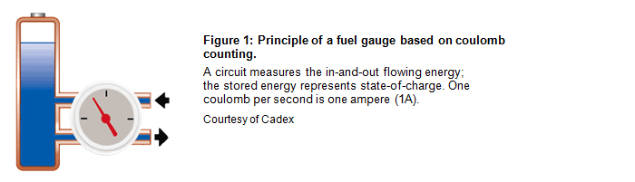
Coulomb counting should be flawless but it is not perfect. If, for example, a battery was charged for 1 hour at 1 ampere, the same amount of energy should be available on discharge, and this is not the case. Inefficiencies in charge acceptance, especially towards the end of charge, as well as losses during discharge and storage reduce the total energy delivered and skew the readings. The available energy is always less than what has been put into the battery.
The single-wire system stores the battery code and tracks battery data that typically includes voltage, current, temperature and state-of-charge information. Because of the relatively low hardware cost, the single-wire system is attractive for price-sensitive devices such as measuring instruments, mobile phones, two-way radios, cameras and scanners.
Most single-wire systems have their own protocol and use a customized charger. The Benchmarq single-wire solution, for example, cannot measure the current directly; state-of-health (SoH) measurement is only possible when “marrying” the host to a designated battery.
The System Management Bus (SMBus) represents a concerted effort to agree on one communications protocol and one set of data. Derived from I2C, the Duracell/Intel smart battery system was standardized in 1995 and consists of two separate lines for data and clock. I2C (Inter-Integrated Circuit) is a multi-master, multi-slave, single-ended, serial computer bus invented by Philips Semiconductor. Figure 3 shows the layout of the two-wire SMBus system.

The philosophy behind the SMBus battery was to remove charge control from the charger and assign it to the battery. With a true SMBus system, the battery becomes the master and the charger the slave, obeying the command of the battery. This enables a universal charger to service present and future battery chemistries by applying correct charge algorithms.
During the 1990s, several standardized SMBus battery packs emerged, including the 35 and 202 (Figure 4). Manufactured by Sony, Hitachi, GP Batteries and others, these interchangeable batteries were designed to power a broad range of portable devices, such as laptops and medical instruments. The idea was solid but standardization diverged as most manufacturers began building their own packs.
To prevent unauthorized batteries from infiltrating the market, some manufacturers add a code to exclude other pack vendors. A few manufacturers go so far as to invalidate the battery when a given cycle count is reached. A warning before the pending end-of-life is given by most of these systems.
An SMBus battery contains permanent and temporary data. The battery makers program the permanent data into the battery, which includes battery ID, battery type, manufacturer’s name, serial number and date of manufacture. The temporary data is added during use and contains cycle count, usage pattern and maintenance requirements. Some of the information is kept, while other data is renewed throughout the life of the battery. The voltage is typically measured in 1mV increments; the current resolution is 0.5mA; temperature accuracy is about ±3ºC.
Smart battery chargers are divided into Level 1, 2 and 3. Level 1 has been discontinued because it did not provide chemistry-independent charging and it only supported a single chemistry. A Level 2 charger is fully controlled by the Smart Battery and acts as an SMBus slave, responding to voltage and current commands from the Smart Battery. Level 2 also serves as in-circuit charging, a practice that is common in laptops. Another use is a battery with a built-in charging circuit. In Level 2, battery and circuit are married to each other.
A level 3 charger can interpret commands from a Smart Battery, as is done with Level 2, and also act as master. In other words, the Level 3 charger can request charging information from the Smart Battery but it can also impose its own charging algorithm by responding to the “chemical” battery. Most industrial smart chargers are based on the hybrid type Level 3.
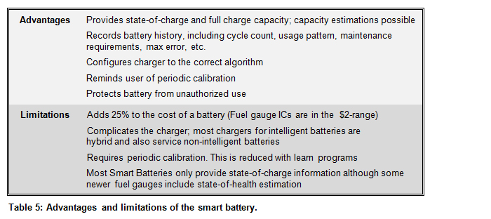
Some lower-cost chargers have emerged that accommodate SMBus batteries, but these may not be fully SBS compliant. Manufacturers of SMBus batteries do not endorse this shortcut because of safety concerns. Applications such as biomedical instruments, data collection devices and survey equipment lean towards Level 3 chargers with full-fledged charge protocols. Table 5 lists the advantages and limitations of the smart battery.
Simple Guidelines for Using Smart Batteries
A speaker at a battery conference once said, “The battery is a wild animal and artificial intelligence domesticates it.” A battery is illusive and does not exhibit visible changes as part of usage; it looks the same when fully charged or empty, new or old and in need of replacement. A car tire, in comparison, distorts when low on air and indicates end-of-life when the treads are worn.
Battery users imagine a battery pack as being an energy storage device that resembles a fuel tank dispensing liquid fuel. For simplicity reasons, a battery can be seen as such; however, measuring stored energy from an electrochemical device is far more complex.
While an ordinary fuel gauge measures in-and-out-flowing liquid from a tank of a known size with minimal losses, a battery fuel gauge has unconfirmed definitions and only reveals the open circuit voltage (OCV), which is a fickle reflection of state-of-charge (SoC). To compound the problem, a battery is a leaky and shrinking vessel that loses energy and takes on less content with each recharge. As the capacity fades, the specified Ah (ampere-hours) rating no longer holds true. Nor can the fuel gauge assess the capacity by itself; the reading always shows full after recharge even if the capacity has dropped to half the specified Ah.
The simplest method to measure state-of-charge is reading voltage, but this can be inaccurate as load currents pull the voltage down during discharge. The largest challenge is the flat discharge voltage curve on most lithium and nickel-based batteries. Temperature also plays a role; heat raises the voltage and a cold temperature lowers it. Agitation by a previous charge or discharge causes further errors and the battery needs a few hours rest to neutralize.
Most batteries for medical, military and computing devices are “smart.” This means that some level of communication occurs between the battery, the equipment and the user. The definitions of “smart” vary among manufacturers and regulatory authorities, and the most basic smart battery may contain nothing more than a chip that sets the charger to the correct charge algorithm. In the eyes of the Smart Battery System (SBS) forum, such a battery cannot be called smart; it must also provide a SoC indication.
Safety is a key design objective and the concept behind SBS is to place system intelligence inside the battery pack. The SBS battery thus communicates with the charge management chip in a closed loop. In spite of this digital supervision, most SBS chargers also rely on analog signals from the chemical battery to terminate the charge when the battery is full. Furthermore, redundant temperature sensing is added for safety reasons.
Benchmarq was the first company to offer fuel-gauge technology in 1990. Today, many manufacturers offer integrated circuit (IC) chips in single-wire and two-wire systems, also known as System Management Bus (SMBus).
State-of-charge estimations in a smart battery commonly include coulomb counting, a theory that goes back 250 years when Charles-Augustin de Coulomb first established the “Coulomb Rule.” Figure 1 illustrates the principle of coulomb counting, measuring in-and-out flowing energy. One coulomb (1C) equals one ampere (1A) per second. Discharging a battery at 1A for one hour equates to 3,600C. (Not to be confused with C-rate.)
Coulomb counting should be flawless but it is not perfect. If, for example, a battery was charged for 1 hour at 1 ampere, the same amount of energy should be available on discharge, and this is not the case. Inefficiencies in charge acceptance, especially towards the end of charge, as well as losses during discharge and storage reduce the total energy delivered and skew the readings. The available energy is always less than what has been put into the battery.
Single-wire Bus
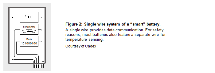
The single-wire system, also known as 1-Wire, communicates through one wire at low speed. Designed by Dallas Semiconductor Corp., the 1-Wire combines data and clock into one line for transmission; the Manchester code, also known as phase coding, separates the data at the receiving end. For safety reasons, most batteries also run a separate wire for temperature sensing. Figure 2 shows the layout of a single-wire system.The single-wire system stores the battery code and tracks battery data that typically includes voltage, current, temperature and state-of-charge information. Because of the relatively low hardware cost, the single-wire system is attractive for price-sensitive devices such as measuring instruments, mobile phones, two-way radios, cameras and scanners.
Most single-wire systems have their own protocol and use a customized charger. The Benchmarq single-wire solution, for example, cannot measure the current directly; state-of-health (SoH) measurement is only possible when “marrying” the host to a designated battery.
System Management Bus
The System Management Bus (SMBus) represents a concerted effort to agree on one communications protocol and one set of data. Derived from I2C, the Duracell/Intel smart battery system was standardized in 1995 and consists of two separate lines for data and clock. I2C (Inter-Integrated Circuit) is a multi-master, multi-slave, single-ended, serial computer bus invented by Philips Semiconductor. Figure 3 shows the layout of the two-wire SMBus system.The philosophy behind the SMBus battery was to remove charge control from the charger and assign it to the battery. With a true SMBus system, the battery becomes the master and the charger the slave, obeying the command of the battery. This enables a universal charger to service present and future battery chemistries by applying correct charge algorithms.
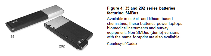
During the 1990s, several standardized SMBus battery packs emerged, including the 35 and 202 (Figure 4). Manufactured by Sony, Hitachi, GP Batteries and others, these interchangeable batteries were designed to power a broad range of portable devices, such as laptops and medical instruments. The idea was solid but standardization diverged as most manufacturers began building their own packs.
To prevent unauthorized batteries from infiltrating the market, some manufacturers add a code to exclude other pack vendors. A few manufacturers go so far as to invalidate the battery when a given cycle count is reached. A warning before the pending end-of-life is given by most of these systems.
An SMBus battery contains permanent and temporary data. The battery makers program the permanent data into the battery, which includes battery ID, battery type, manufacturer’s name, serial number and date of manufacture. The temporary data is added during use and contains cycle count, usage pattern and maintenance requirements. Some of the information is kept, while other data is renewed throughout the life of the battery. The voltage is typically measured in 1mV increments; the current resolution is 0.5mA; temperature accuracy is about ±3ºC.
Smart battery chargers are divided into Level 1, 2 and 3. Level 1 has been discontinued because it did not provide chemistry-independent charging and it only supported a single chemistry. A Level 2 charger is fully controlled by the Smart Battery and acts as an SMBus slave, responding to voltage and current commands from the Smart Battery. Level 2 also serves as in-circuit charging, a practice that is common in laptops. Another use is a battery with a built-in charging circuit. In Level 2, battery and circuit are married to each other.
A level 3 charger can interpret commands from a Smart Battery, as is done with Level 2, and also act as master. In other words, the Level 3 charger can request charging information from the Smart Battery but it can also impose its own charging algorithm by responding to the “chemical” battery. Most industrial smart chargers are based on the hybrid type Level 3.
Some lower-cost chargers have emerged that accommodate SMBus batteries, but these may not be fully SBS compliant. Manufacturers of SMBus batteries do not endorse this shortcut because of safety concerns. Applications such as biomedical instruments, data collection devices and survey equipment lean towards Level 3 chargers with full-fledged charge protocols. Table 5 lists the advantages and limitations of the smart battery.
Simple Guidelines for Using Smart Batteries
- Calibrate a smart battery by applying a full discharge and charge every 3 months or after every 40 partial cycles. Batteries with impedance tracking provide a certain amount of self-calibration.
- A fuel gauge showing 100 percent SoC does not automatically assure a good battery. The capacity may have faded to 50 percent, cutting the runtime in half. A fuel gauge can give a false sense of security.
- If possible, replace the battery with the same brand to avoid incompatibility issues with the device and/or charger. Always test the battery and the charger before use.
- Exercise caution when using a smart battery that does not indicate state-of-charge correctly. This battery may be faulty or is not fully compatible with the equipment.